Is it possible for one transistor to switch between two loads?
This is my answer to my first Codidact question Is it possible for one transistor to switch between two loads?
When, two months ago, I accidentally found out about the new Codidact platform, I was happy and decided to take part in it. I wanted to mark this event with an interesting question that would arouse the interest of visitors to the new platform. Thus I remembered an interesting inventive idea from the distant past that then brought me a patent.
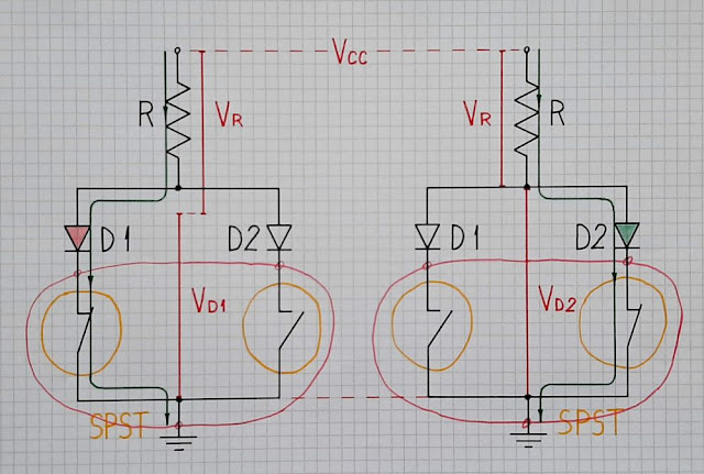
My idea was simple. In 1984, I got a patent for an LED voltage indicator where two transistors controlled three LEDs. Now, inspired by the new EE platform, I began to realize the idea in a more general way and to think about it. That is how the idea for this question was born…
Briefly, an LED is supplied by a current and is lit. An SPST switch (transistor) connects another LED with lower VF in parallel. It diverts the current of the first LED, turns it off and lights up. As though, the first LED acts as a NC SPST switch that complements the NO SPST (transistor) switch... and the combination of them acts as a composite SPDT switch. And I decided to ask this question..
I had two possibilities - to show my possible answer or to wait for others to show their solutions. I chose the latter... and I got a negative reaction. Another time, somewhere else, I chose the former... but result was the same - negative reactions. I thought it would be different here, so I was enthusiastic to do something more original and interesting... but it did not turn out the way I imagined...
Question
The output collector-emitter part of a transistor can be thought of as a 2-terminal SPST switch controlled by the input base-emitter voltage or base current. So this transistor switch can control only a single collector load.
Is it possible to make the transistor act as a 3-terminal SPDT switch? If so, one transistor will be able to control (switch between) two loads.
In general, can a SPST switch act as a SPDT switch?
Answer
To best reveal my idea, I will present it in the form of an inventive scenario of 4 steps.
In the beginning, imagine we have two LEDs - red (with VF = 1.5 V) and green (VF = 2.5 V), and we want to switch them so that when one is on the other is off and vice versa.
1. One SPDT controls two LEDs. The most obvious solution is to switch the two LEDs with one SPDT switch - Fig. 1.
 |
| Fig. 1. One SPDT controls two LEDs |
Depending on the switch position, the current is steered between the two LEDs. The voltage drop across them varies between 1.5 V and 2.5 V when we switch them... but so far this does not impress us.
The problem is that we can not implement an SPDT switch by one BJ transistor since its collector-emitter part acts as a simple 2-terminal SPST switch.
2. Two SPST control the LEDs. But we can assemble an SPDT switch by two SPST switches - Fig. 2, and they can be implemented by transistors.
 |
| Fig. 2. Two SPST control the LEDs |
We have to control them so that when one switch is on the other is off and vice versa. Thus there are two valid combinations.
3. "Invalid" switch combinations (both off or on). But with this implementation, two more combinations are possible, in which we may inadvertently fall. First, both switches can be off. Second, which is more interesting, is the combination when both switches are on - Fig. 3.
 |
| Fig. 3. "Invalid" switch combinations (both off or on) |
The threshold voltage of the red LED is lower than that of the green one. Therefore, when connected in parallel, the current is steered to the red LED. Can not we use this phenomenon to simplify the circuit?
 |
| Fig. 4. One SPST controls the LEDs |
Now the left switch turns on the red LED that, in its turn, turns off the green LED.
5. Application. I have implemented this idea in the circuit of a 3-LED voltage indicator where two transistors control three LEDs. A fragment of this circuit is shown in Fig. 5 in the case the input voltage VIN is positive.
 |
| Fig. 5. The idea is implemented in the circuit of a 3-LED voltage indicator (at positive input voltage). |
 |
| Fig. 6. The 3-LED voltage indicator at negative input voltage. |
You question is clear: "How can one bipolar transistor switch between two (or even more) LEDs (or other loads)?
ReplyDeleteBut your question contains a couple of technical terms I don't know. eg. What are SPST, SPDT, NC?
I would appreciate a circuit diagram which would at least refresh my memory.
Cheers.
Your Blogger account title is too specific, so would not attract audience or Google searches. I would suggest to use boarder names such as "Innovative Bipolar Transistor Switching LED Tricks" or even boarder or eye-catching alternatives.
ReplyDeleteI have adopted to use the original names of the materials as they are on the sites ...
Delete