Posts

Showing posts from December, 2021

Amplification and bias point

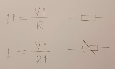
  This is  my answer  to SE EE question  Amplification and bias point . My answer I will answer only the first part of your first question because it is very fundamental and deserves special attention: "Can the amplified voltage exceed the power supply voltage...?" The answer is simple: The amplified voltage cannot exceed the supply voltage because it is a part of it. Literally speaking, the "voltage amplification" is not an amplification; it is an attenuation. It is just a clever trick with which we get an output voltage that is proportionally higher ("amplified") than the input voltage. How is this done? Amplifier stages are voltage dividers controlled by the input voltage and powered by a higher (supply) voltage. They are implemented by so-called "active elements" (transistors) which in fact are voltage-controlled "resistors". So, when the small input voltage slightly varies, the output voltage significantly varies from zero to the s

Why would I want to use a differential op amp configuration while amplifying differential signals?

Image
This is  my answer  to SE EE question  Why would I want to use a differential op amp configuration while amplifying differential signals? My answer Your question is "philosophical" and therefore requires a "philosophical" answer:-) You are actually asking, "What is the idea behind the classic op-amp instrumentation amplifier?" The best way to show it is by reinventing the circuit step by step. Here is my story... Step 1: Single-ended amplifier It is assumed that the two basic circuits of op-amp amplifiers with negative feedback have already been "invented":  1. Non-inverting amplifier  2. Inverting amplifier This is another (no less interesting) story, but now let's just mention the trick with which this was done - in the basic circuits of a follower (K = 1) and inverter (K = -1) an attenuation is introduced in the negative feedback. Compensating for it, they have become amplifiers. Step 2: Imperfect differential amplifier We need a device th

Calculate V for given circuit

Image
 This is my answer to SE EE question Calculate V for given circuit . My answer I further developed jonk's idea of a "geometric drawing" of the circuit diagram that would help find the answer... Step 1. The idea of this representation - Fig. 1, comes from the geometric notion of voltage, which is based on the analogy called "water tower". According to this idea, we represent the positive voltages and the parts of the circuit with such voltages above the zero reference level (ground) and the negative ones - below it. We can go even further by drawing diagrams in proportion to voltages using a certain scale factor V/unit. Fig. 1. A circuit with real diodes For this purpose, I accompany these "geometric-driven circuit diagrams" with a more stylized representation of voltages through vertical sections with proportional height, which I call voltage bars . Sometimes I mark voltage levels with thin red lines (as in Fig. 1); usually, it is sufficient to show

Where do input bias currents flow?

Image
This is my answer to SE EE question AC coupled differential op amp bias current return path . My answer The best way to understand and explain circuits in an intuitive way is to show where currents flow  and what voltages are in circuits  and inside resistors . Here the OP is interested in where the input bias currents flow. That is why I have shown in Fig. 1 only their paths on a simplified conceptual circuit diagram of a part of an internal op-amp structure. Fig. 1. A conceptual op-amp circuit diagram with input bias currents visualized. It can be supplemented with (thicker) loops representing the collector currents flowing in the input and output stage - Fig. 2. Fig. 2. A conceptual op-amp circuit diagram with all currents visualized. It is interesting to see that the input bias current I- entering the inverting op-amp input is provided by both the positive power supply V+ and negative V- (connected in series) while the input bias current I+ entering the non-inverting input is prov

Why does the collector current depend linearly on the base current?

Image
It is well known that there is a linear relationship between the BJT collector and base current (Ic = beta x Ib). It would be interesting to explain it in an intuitive way. The power of such a "philosophical" approach is that it can explain various specific implementations. The idea In the BJT, the base-emitter voltage controls the collector current in an exponential manner. So, if we directly drive the base-emitter junction by a perfect voltage source, the bare transistor can be thought as an "antilog voltage-to-current converter". If we drive the base-emitter junction by a voltage source through a resistor or by a perfect current source, we will control indirectly the base-emitter voltage... and it will control the collector current as usual. So the base-emitter junction serves here as a "log current-to-voltage converter". The conclusion is that, in this arrangement, there are two cascaded (reverse and direct) non-linear convertors. .. and the overall re

How does a transistor maintain a constant current?

Image
In contrast to diodes that maintain a relatively constant voltage when the current through them varies, a fundamental property of all types of transistors (BJT, FET...) is to maintain a relatively constant current when the voltage across them varies. How do they do that? As in the case of diodes, this question can be answered specifically by considering the processes in the semiconductor device. But again it would be interesting to explain this on a conceptual level by revealing the basic idea. As I have already said, this "philosophical" approach has several advantages: first, it does not require in-depth knowledge of semiconductor devices; second, it would be applicable to all 2-terminal devices that have this property. I will do this using the concept of "dynamic resistance". Generally speaking, a transistor behaves like a resistor that interferes with current creating a voltage drop and heat loss. In the initial steep part of its output IV curve, this "res