Posts

Showing posts from November, 2021

How does a diode maintain a constant voltage?

Image
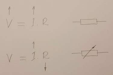
A fundamental property of all types of diodes (silicon, germanium, Schottky, LEDs, Zener ...) is to maintain a relatively constant voltage when the current through them varies. How do they do that? This question can be answered specifically by considering the processes in the semiconductor PN junction. Also, it would be interesting to explain this on a conceptual level by revealing the basic idea. This "philosophical" approach has several advantages: first, it does not require in-depth knowledge of semiconductor devices; second, it would be applicable to all 2-terminal devices that have this property. I will do this using the concept of "dynamic resistance". In the most general sense, a diode behaves like a resistor that interferes with current creating a voltage drop and heat loss. In the initial sloping part of its IV curve, this "resistor" has a relatively constant high resistance. And if it was really a resistor, the curve would continue in the same di

ЛУ5 ППЕ ИТИ 2021

  ЛУ 5: Приложни схеми с диоди I. Основни електрически понятия 1. Електрически ключ: нормално отворен, нормално затворен, превключващ, неуправляем, управляем. Волт-амперна характеристика на управляем ключ (вентил). Опростявания (пренебрегване на VF). 2. Мостова превключвателна схема за реверсиране на консуматори II. Изследване на схемите 1. Чрез осцилоскоп на времедиаграми с помощта на генератор (трансформатор на 50 Hz) и осцилоскоп в режим YT (развивка във времето) на предавателни характеристики чрез генератор (трансформатор на 50 Hz) и осцилоскоп в XY режим    2. Чрез система МИКРОЛАБ III. Диодът като ключ 1. Волт-амперна характеристика на диод, използван като ключ . Опростявания (пренебрегване на Ri). 2. Приложни диодни схеми: Изправители: Еднополупериоден изправител без изглаждащ кондензатор с изглаждащ кондензатор Двуполупериоден изправител (с двойна намотка на трансформатора; схема Грец) без изглаждащ кондензатор с изглаждащ кондензатор Диодни ограничители: Последователни огран

ЛУ4 ППЕ ИТИ 2021

Image
 ЛУ 4: Автоматично изследване на диоди I. Основни електрически понятия 1. Променливо напрежение Интуитивно обяснение - вариращ източник на напрежение, който периодично си сменя полярността Стойности: моментна, максимална, ефективна 2. Трансформатор Идея и устройство Приложения: намаляване на напрежение, галванично отделяне 3. Резистор като преобразувател ток-напрежение II. Графични измервателни уреди 1. Аналогов осцилоскоп Основни сведения: идея, принцип на действие, устройство, командни органи Режими на работа Развивка във времето XY режим Калибриране 2. Цифров осцилоскоп 3. Компютърна система за снемане на характеристики III. Измисляне на опитната постановка 1. Снемане на ВАХ с аналогов осцилоскоп в XY режим Устройство на аналоговия осцилоскоп Tektronix 2235A. Особености на XY режима на работа. Идея на опитната постановка – „разгъване” с променлив сигнал, генериран от трансформатор (50 Hz): Необходими са ни общо три елемента, свързани последователно - променлив източник на напрежение

What are voltages inside resistors?

Image
See also a related RG discussion and Codidact paper . By the mid-1990s, I had already developed my own philosophy about electronic circuits, and I decided it was time to share it with my colleagues. In the spring of 1997, I presented a series of three papers at the XXXII Scientific Conference on Communication, Electronic and Computer Systems at the Technical University of Sofia. The second of these was dedicated to my idea of visualizing circuit operation through interactive voltage diagrams . In this post, I will tell you about this venture of mine. Need to visualize voltage distribution Once visualized the voltages of the internal circuit points , we can go even further and "enter" inside resistors to visualize the voltages across the resistive film. This will allow us to see some interesting points (for example, virtual ground ), the operation of well-known electrical devices (potentiometer, resistive summer) and electronic circuits (inverting, non-inverting, differentia

What are voltages in circuits?

Image
See also a related RG discussion and Codidact paper . By the mid-1990s, I had already developed my own philosophy about electronic circuits, and I decided it was time to share it with my colleagues. In the spring of 1997, I presented a series of three papers at the XXXII Scientific Conference on Communication, Electronic and Computer Systems at the Technical University of Sofia.  The first of these was devoted to my heuristic course on analog circuits , in which I had implemented my circuit philosophy. There I shared  my idea of visualizing circuit operation through interactive voltage bars . In this post I will tell you about this venture of mine. Need to Visualize Voltages I hope I have convinced you that a powerful technique for explaining circuits in an intuitive way is to show where currents flow . But since currents are created by voltages, it is even more important to show what voltages of the internal circuit points are. First Ideas Voltages, like currents, are invisible... a

ЛУ3 ППЕ ИТИ 2021

Image
  ЛУ 3: Ръчно изследване на диоди I. Основни електрически понятия 1. Резисторът като пасивен преобразувател: напрежение-ток и съпротивление-ток; ток-напрежение и съпротивление-напрежение 2. “Pull-up” и “pull-down” резистор: Идея (интуитивно обяснение на произхода на имената) Приложения 3. Делител на напрежение: "Изобретяване”: от натоварен реален източник на напрежение чрез каскадно свързване на преобразуватели напрежение-ток и съпротивление-ток чрез последователно свързване на “pull-up” и “pull-down” резистори Изследване: Без товар (на празен ход) С товар (резистори с различни стойности или няколко с еднаква стойност паралелно) Разглеждане на желани приложения и нежелани проявления в електронните схеми 4. Потенциометър "Изобретяване” чрез:  вертикално слепване на два резистора снемане на потенциална диаграма на съпротивителен проводник ( експеримент на Ом ) Изследване: Без товар (на празен ход) С товар - резистор, комбинация от резистори Изследване на необичайни потенциометр

Where do currents flow in circuits?

Image
I dedicate this story to my students from group 48a (see also a related RG discussion  and Codidact paper ) Need to visualize currents I have long understood that one of the most important techniques to understand circuits is to see where currents flow inside them (in circuit theory, this is considered unimportant and, at best, currents are represented by small arrows with arbitrary direction). First ideas The problem is that currents, like other electrical quantities, are invisible... and to show them, we have to visualize their paths, directions and magnitudes. That is why, in the late 80's , for the purposes of true understanding, I began representing current paths on circuit diagrams through closed directed lines. An example is the circuit diagram of an op-amp inverting amplifier from my Student Manual for the Analog Circuitry (1989): Another electrical "law" Even then, I realized how important is to draw power supplies because currents start from the positive termina