Calculate V for given circuit
This is my answer to SE EE question Calculate V for given circuit.
My answer
I further developed jonk's idea of a "geometric drawing" of the circuit diagram that would help find the answer...
Step 1. The idea of this representation - Fig. 1, comes from the geometric notion of voltage, which is based on the analogy called "water tower". According to this idea, we represent the positive voltages and the parts of the circuit with such voltages above the zero reference level (ground) and the negative ones - below it. We can go even further by drawing diagrams in proportion to voltages using a certain scale factor V/unit.
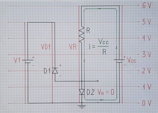 |
Fig. 1. A circuit with real diodes |
For this purpose, I accompany these "geometric-driven circuit diagrams" with a more stylized representation of voltages through vertical sections with proportional height, which I call voltage bars. Sometimes I mark voltage levels with thin red lines (as in Fig. 1); usually, it is sufficient to show only some typical voltage levels.
In addition to voltages, it is very important for understanding circuits to see where currents flow. For this purpose, they must be drawn with complete closed paths (loops) and this requires the voltage sources (power supplies, input sources) be drawn.
Step 2. For the sake of understanding, schematics should be as simple as possible. More complex semiconductor devices should be replaced by simpler equivalent electrical devices. In our case, if saying "ideal diode" OP means a diode with zero (negligible) forward voltage, we replace the diodes with "piece of wire" (short circuit) or "nothing" (open circuit). In order to show the connection between the original and modified circuit, we can hint at the semiconductor devices by drawing them in pale gray - Fig. 2.
 |
Fig. 2. A circuit with hinted diodes |
Step 3. Towards the end of the explanation, we can begin to "clean" the schematic from "unnecessary" voltage bars, current loops, etc...
 |
Fig. 3. A circuit without diodes |
Step 4. So we can come to a very interesting final conclusion. In the specific OP circuit, it turns out that, seen from the side of the load, it is actually... a "piece of wire".
 |
Fig. 4. What actually the circuit is |
Comments
Post a Comment