Why would I want to use a differential op amp configuration while amplifying differential signals?
This is my answer to SE EE question Why would I want to use a differential op amp configuration while amplifying differential signals?
My answer
Your question is "philosophical" and therefore requires a "philosophical" answer:-)
You are actually asking, "What is the idea behind the classic op-amp instrumentation amplifier?" The best way to show it is by reinventing the circuit step by step. Here is my story...
Step 1: Single-ended amplifier
It is assumed that the two basic circuits of op-amp amplifiers with negative feedback have already been "invented":
1. Non-inverting amplifier
2. Inverting amplifier
This is another (no less interesting) story, but now let's just mention the trick with which this was done - in the basic circuits of a follower (K = 1) and inverter (K = -1) an attenuation is introduced in the negative feedback. Compensating for it, they have become amplifiers.
Step 2: Imperfect differential amplifier
We need a device that amplifies the difference between two input voltages. So we start looking for a second input with the opposite effect in each of the two configurations. We have two options to do so:
- In the circuit of the non-inverting amplifier we insert the second source between the input resistor R1 and ground. Thus we obtain another but inverting input.
- In the circuit of the inverting amplifier we insert the second source between the non-inverting input and ground. Now we obtain another but non-inverting input.
The result is the same differential configuration.
Step 3: Differential amplifier
But there is a problem - the gain of the non-inverting input is one unit higher than the gain of the inverting input (this is also interesting to explain... but let's not be now). We start looking for a way to equalize the gain of the two inputs. We have two options:
- We can decrease the gain of the non-inverting input by one through a voltage divider. Thus we get the classic 4-resistor circuit of a simple differential amplifier (shown on the right side of the OP's circuit).
- We can increase the gain of the inverting input by one through an additional non-inverting amplifier and we get Spehro's circuit solution.
At the time, they chose the first solution for obvious reasons - not only because it is more beautiful and symmetrical:-) but simply because operational amplifiers were expensive. Let's follow them...
Step 4: Improved differential amplifier
But the simple 4-resistor differential amplifier has a significant drawback - low input resistance (in addition, it is different for both inputs). The worst thing in this case is that the difference in the internal resistances of the input sources unbalances the circuit.
The first thought that comes to mind to solve this problem, of course, is to put op-amp voltage followers before the circuit inputs. This solves the input resistance problem... but a new problem arises when we need more significant gain - the ability of the second stage to amplify is exhausted and we must make the first stage also amplify.
Step 5: Instrumentation amplifier prototype
The straightforward solution is to make the input followers amplify, ie, to turn them into non-inverting amplifiers by inserting voltage dividers between the op-amp outputs and inverting inputs. However, a new problem arises - the common-mode gain.
Simply put, we would like the input stage to amplify the input voltages when they change in the opposite direction and not to amplify them when they change in the same direction with the same rate. How do we do it?
Step 6: Instrumentation amplifier
The famous "long-tailed pair" can help us. For this purpose, we simply combine the two lower resistors of the voltage dividers into one (R1 in the OP's circuit). Now the circuit has a different behavior depending on how we change the input voltages:
1. Differential mode. When the voltages change in the opposite direction, the so-called "virtual ground" (zero voltage point) appears in the middle point inside R1 and the gain is maximum (the input op-amp stages act as non-inverting amplifiers). You can "see" this point if you "open" R1... or just imagine the voltage distribution along R1 resistive film; I call it a voltage diagram. See, for example, the picture below extracted from a Wikibooks story.
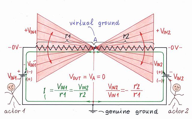 |
Voltage diagram - differential mode |
2. Common mode. If the input voltages change in the same direction with the same rate, the voltages of all op-amp inputs, all points inside R1 (including the middle point) and both op-amp outputs change in the same way; as they say, they are equipotential. As a result, the input op-amp stages act as voltage followers (K = 1).
 |
| Voltage diagram - common mode |
You can see "live" voltage diagrams of these modes in the movie].
----------
This was my story about the famous op-amp instrumentation amplifier. If there is interest, I can illustrate it with more pictures.
Comments
Post a Comment