Class AB power amplifier from "Electronic Devices" by Thomas L. Floyd
This is my answer to SE EE question Class AB power amplifier from "Electronic Devices" by Thomas L. Floyd.
My answer
Imagination is more important than knowledge. A. Einstein.
How do we visualize the circuit operation?
The notion of voltage as height is the most common idea of this electrical quantity (which is why we say "high" and "low" and not "big" and "small" voltage). It originates from the gravitational or "water tower" analogy where the height of a water column is proportional to the potential energy of the water.
According to this approach, we can explain this circuit "geometrically" by imagining voltages as vertical segments (voltage bars) with a height proportional to the voltage value.
It is well known that diodes maintain (approximately) constant voltage at their terminals (see this intuitive explanation). So, the voltage drops across them can be represented by segments of constant length (0.7 units) and, accordingly, the string of three diodes in series - as a segment of three times the length (3 x 7 = 2.1 units). Similarly, the voltages across capacitors can be represented by shock absorbers that become stiff for rapid changes of the input signal (AC). The voltages across resistors can be represented by segments of varying length that change when the current varies.
Investigating the circuit operation
We can go even further by imagining the diode segment as a "rod" of constant length and the resistor segment as a spring of variable length (mechanical analogy). Then, figuratively speaking, we (input voltage source) have three possible ways to control the circuit of this "AB power amplifier":
- We can move (pull up and down) both the upper and lower ends of the "rod" (the input voltage variations are applied simultaneously to both bases). This is the idea of Fig. 1 from Floyd's bestseller where the AC input voltage is applied through two capacitors simultaneosly to both bases.
- We can move the lower end of the "rod" (the input voltage variations are applied to the lower end of the diode string). This is the idea of Fig. 2 from the book where the input voltage is applied through a booster to the lower end of the diode string.
- We can move the middle of the "rod" (the input voltage variations are applied to the middle of the diode string). This beautiful symmetric circuit solution is widely used in op-amp internal structures where the diode string is powered by a current source and the input voltage source "moves" the midpoint of the diode string. I have examined it in detail in another SE EE answer of mine. Here is one of the figures that illustrates the case when the input voltage changes to negative.
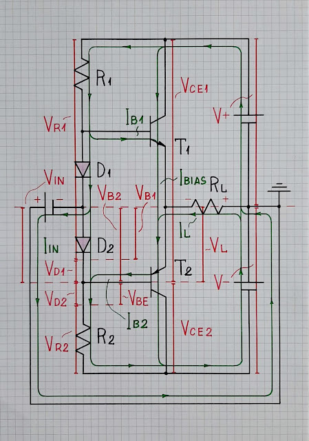 |
Negative input voltage As can be seen from the figure, it is no less interesting and useful to show the current paths in the diagram (I have considered in detail this visualization technique in another post in my blog). I would also illustrate Fig. 2 this way, with voltage bars and current loops, if there is interest in it. |
Comments
Post a Comment