Where has this current gone in my current-voltage converter?
This is my answer to SE EE question Where has this current gone in my current-voltage converter?
My answer
The necessary philosophy
I read these answers full of technical details and wonder how it is possible not to reveal the simple but brilliant idea behind this op-amp circuit consisting only of a resistor and op-amp? I realized it 30 years ago (Fig. 1) and with its help I was able to understand and explain many other op-amp circuits.
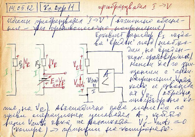 |
Fig. 1. A conceptual picture of an active current-to-voltage converter from my archive (1992). Here is the translated text: |
Basic idea
The idea is obvious: To measure the current I by a voltmeter, we break the circuit, insert a resistor RI and measure the voltage drop across it (VR = I.RI). But this voltage introduces an error since it is subtracted from the input "current-creating" voltage VIN and the current decreases. So we decide to destroy it by adding an equivalent voltage V = VR. For this purpose, we break again the circuit and insert a varying voltage source producing the compensating voltage V. This voltage is added to the input voltage and the error is eliminated - Fig. 2.
 |
Fig. 2. Full conceptual circuit of four elements in a loop (the picture is taken from a similar story about the inverting amplifier). Note the two voltages are summed in a series manner. Op-amp implementationSo the (properly supplied) op-amp output acts as a small variable "battery" connected in series to the resistor (Fig. 3) that adds the compensating voltage VOUT = I.R in the circuit. And, of course, the input current will flow through this "battery".  |
Fig. 3. Op-amp implementation of the idea
To close the current path, we have to draw the respective power source - negative if the input voltage is positive (like in Fig. 3) and positive if the input voltage is negative.
How does the op-amp do it?
It is interesting to see how the op-amp copies the voltage drop VR at its output. According to KVL, we can see in Fig. 2 and Fig. 3 a loop of three voltages - VR, VOUT and VA. The op-amp changes VOUT so that to keep VA zero (negative feedback). As a result, VOUT = VR.
Another clever trick is that we use the compensating voltage as a buffered, grounded and inverted output voltage (the last feature is a "gift" that is not always desired).
Visualized operation
To illustrate the circuit operation in a more attractive way, we can "geometrically" draw the circuit diagram - Fig. 4.
 |
Fig. 4. A "geometrical" representation of the op-amp current-to-voltage converter In this representation, the "positive circuit part" is drawn above the zero voltage level (ground) and the "negative circuit part" is drawn below the ground. The voltages are represented by voltage bars in red and the currents - by current loops in green and blue. Note something very important - the input current (in green) does not flow through the load. The load current (in blue) is provided only by the negative supply source, i.e., the load does not consume current from the input voltage source. This is a big advantage of the active op-amp circuit compared with the passive one (resistor). Circuit evolutionThe power of this step-by-step building approach is that it shows the circuit evolution from the humble 1-resistor passive circuit to the more sophisticated op-amp circuit. We see this is not a new circuit; it is an improved old circuit. So the active op-amp current-to-voltage converter consists of a passive current-to-voltage converter and helping op-amp. Negative resistance viewpointIf we are curious enough, we can see a similarity between the resistor R and the op-amp output - there is the same voltage I.R across them; so both behave as resistors. But while the resistor subtracts its voltage drop from the input voltage, the op-amp adds its output voltage to it. So the op-amp output acts as a negative "resistor" with resistance -R that neutralizes the positive resistance R. The whole circuit (resistor and op-amp) behaves as a "piece of wire"... and the input current flows through this "artificial wire" - Fig. 5. |
 |
Fig. 5. The transimpedance amplifier presented as a "piece of wire" |
Passive vs active version
As a rule, we know the passive is bad and the active is good. But here the passive "circuit" (resistor) has a very significant advantage over the active - it allows to measure currents of large magnitude.
The problem with the active op-amp current-to-voltage converter is that the current passes through its output stage... and the latter must withstand it. That is why the ammeters inside multimeters are not made with the op-amp circuit, no matter how perfect it is, but with the simple passive circuit (a humble resistor between the inputs).
Comments
Post a Comment