Why is the voltage across the resistor R zero during the negative half cycle for a clipper circuit?
I answered this SE EE question yesterday.
My answer
1. Real circuit. The diode D and 4 V voltage source are shown on the schematic but they do nothing during the "negative half cycle". More precisely speaking, the total resistance of the two elements in series is much larger than the resistance R1. A voltage divider with a transfer ratio of about 1 is formed.
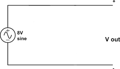
2. Circuit with "redundant" elements removed. So we can remove (erase) the redundant elements from the schematic.
3. Circuit with zeroed resistance. Also, the resistor R1 does nothing during the "negative half cycle"; it behaves like a piece of wire so we can replace it by a piece of wire on the schematic. More precisely speaking, the resistance R1 is much less than the load resistance (not shown in the diagram). A voltage divider with a transfer ratio of about 1 is formed.


Comments
Post a Comment