How does the current and voltage stabilize in a differential amplifier?
This is my answer to the SE EE question about the famous "long-tailed pair".
--------------------
Basic idea
It can be revealed at а functional level by equivalent electrical circuits. In this brilliant circuit solution initially called with the figurative name "long-tailed pair", a total of three sources - two voltage and one current - interact like living beings. In some cases they help each other and in others they oppose each other like people in the game tug of war.
Implementation
The two voltage sources are implemented by the source followers Q1 and Q2. The current source (or, more precisely speaking, current sink) is implemented by another transistor (not shown in the OP's circuit). So these sources are not actually true sources (producing power) but dynamic resistors that only regulate voltage and current (see more about this approach in another related question and answer of mine).
Conceptual circuit
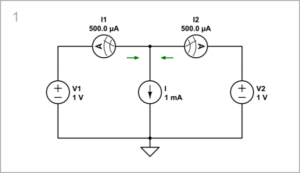
To simulate the circuit, actually we have to connect three sources in parallel. The problem is that "ideal" voltage sources should not be connected in parallel because even with the smallest difference in their voltages, a high current will flow between them (that is why CircuitLab does not allow it). To mitigate the conflict between them, we need to insert small resistances in series. For this purpose, we can use ammeters with some, albeit small, internal resistance (I have set 20 Ω). They will serve as current outputs, and the voltage drops across them can be used as voltage outputs.
 |
| Simulate this circuit – Schematic created using CircuitLab |
Operation
Using this modest setup we will be able to explore all circuit modes. The elements whose quantities we vary as inputs are indicated by an arrow in light gray. Initially, V1 = V2, and the bias 1 mA current splits into two 0.5 mA currents that flow through the sources.
Biasing mode
One of the basic ideas of the differential pair is that the transistors are biased on the emitter side. This is done via a current source (I) because the emitters are not firmly fixed ("immovable") but "shift" when both input voltages change simultaneously in the so-called "common mode". In this way, the bias current will not change when the emitter voltage varies. Initially the bias current is adjusted to 1 mA but let's experiment with two more values of 2 and 3 I = 2 mA: mA to see how the sources react.
I = 2 mA: When we increase the bias current with 1 mA, the voltage does not change because it is set by two constant voltage sources in parallel...
 |
| Simulate this circuit |
I = 3 mA: ... also if we increase it by another 1mA and continue in the same vein.
 |
| Simulate this circuit |
So, in this mode, the two voltage sources cooperate to keep the voltage constant when the current source changes the common current. In this way, they provide ideal load conditions (no voltage variations) for the current source; they act as an "ideal current load".
Reaching equilibrium: In the real (OP's) circuit, the two voltage sources in parallel are implemented as negative feedback circuits (emitter followers). The current source disturbs their outputs and they react to this intervention by simultaneously changing their input gate-source voltages Vgs. The equilibrium is reached when the relation between I and Vgs corresponds to the transistor transfer characteristic.
"Reversed transistor": In this mode, a unique phenomenon of "reversal" through negative feedback is observed. As we all know, the gate-source voltage is the input quantity and the drain (emitter) current is the output quantity. However, here it is reversed - the current is the input quantity, and the voltage Vgs is the output quantity. This is done by the transistor adjusting (via the negative feedback mechanism) its input voltage to match the output current. As a result, the current becomes the input quantity and the voltage Vgs the output quantity. This is not only electrical but a universal phenomenon that we can observe all around us.
Common mode
The differential amplifier is designed with two inputs to be able to distinguish harmful (common-mode) from useful (differential-mode) signals. Let's first examine how the circuit reacts to the former. For this purpose, we have to change simultaneously both input voltages in the same way.
V1 = V2 = 2 V: We see that if we increase the voltage by 1 V...
 |
| Simulate this circuit |
V1 = V2 = 3 V: ... and by another 1 V, the current does not change.
 |
| Simulate this circuit |
So, in this mode, the two voltage sources cooperate to change the voltage while the current source keeps the common current constant. In this way, the current source provides ideal load conditions (no current variations) for the voltage sources; it acts as an "ideal voltage load".
Single-ended mode
This is an intermediate mode in which we change only one input voltage and keep the other constant. It is asymmetrical and less often used.
Increasing V1: I1 increases, I2 decreases.
 |
| Simulate this circuit |
Decreasing V1: I1 decreases, I2 increases.
 |
| Simulate this circuit |
Increasing V2: I2 increases, I1 decreases.
 |
| Simulate this circuit |
Decreasing V2: I2 decreases, I1 increases.
 |
| Simulate this circuit |
So, in this mode, one voltage source resists "passively" when the other tries to change the voltage at the common point of the emitters. The current source is not involved in this.
Differential mode
This is the main (symmetrical and most used) mode in which we change both input voltages but in opposite directions. The two voltage sources actively resist each other while the current source passively "observes".
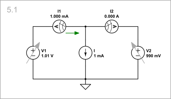
Increasing V1, decreasing V2: As you can see, it only takes 10 mV to change the voltages in one direction...
 |
| Simulate this circuit |
Decreasing V1, increasing V2: ... or the other...
 |
| Simulate this circuit |
... and the bias current is diverted from one voltage source to the other.
Comments
Post a Comment