Which is better - series or parallel rectifier?
This is a copy of my SE EE question and answer.
--------------------
The idea for this question gave me the question - Understanding positive and negative rectifiers. Here I want to summarize the ideas behind the two circuit configurations - series and parallel, hoping to enrich the idea of them through your answers.
 |
| Simulate this circuit – Schematic created using CircuitLab |
 | |
|
I have taken the opportunity to answer my question at the same time as posting it due to the considerable volume of writing.
Trying to see the forest for the trees
So many questions about two simple diode circuits lead us to think that there are some much more general ideas here, some "philosophy". If we can uncover it, we will be able to see the commonality between these particular diode circuits and other seemingly different circuits.
How to switch sources
For the purposes of our intuitive explanations, we can represent the AC input voltage source by two constant voltage sources with opposite polarities - one with a positive voltage for the positive half-wave and the other with a negative voltage for the negative half-wave of the input voltage. For clarity, we will change the polarity by vertically flipping the source and not by changing the sign of the voltage.
Switches
Since the first electrical sources, switches and loads were invented two centuries ago, the two classic switching configurations — series and parallel — emerged. To reveal the idea behind them here, I propose to implement them step by step using ideal, ideal diode, real and real diode switches.
Switching a voltage source in series
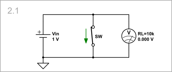
The simplest and most obvious way to switch a voltage source is by connecting the switch SW in series with the source Vin and the load RL (an ammeter with an internal resistance of 10 kΩ) in the schematic below. There is no need for a voltmeter because the input source determines the voltage. Imagine that the state of the switch depends on the polarity of the input voltage as follows:
Vin < 0, SW is open: There is no current flowing and the voltage across the load is zero.
 |
| Simulate this circuit |
Vin > 0, SW is closed: A 0.1 mA current enters the load and a 1 V voltage is applied across it.
 |
| Simulate this circuit |
Switching a voltage source in parallel
Voltage source with internal resistance: And why not try to "turn off" the source (make its voltage zero) by simply shorting it? It can, but if the voltage source is not ideal and it has some internal resistance, e.g. a battery from the CircuitLab library to which we set Ri = 10 Ω. When the switch is closed, the current is diverted from RL to the switch, and the voltage across the load is zero.
 |
| Simulate this circuit |
Resistor current source: This gives us the idea to connect an external resistor Ri in series with the perfect input voltage source. Thus Vin and Ri form a simple current source.
 |
| Simulate this circuit |
Switching a current source in parallel
I will use the case to formulate a rule for controlling the current produced by an "ideal" current source: We cannot stop its current by breaking the circuit (because the voltage will increase to infinity)...
 |
| Simulate this circuit |
... we can only divert the current by shunting the load.
 |
| Simulate this circuit |
Ideal diode switching
Now let's implement the rectifier circuits according to the configurations above by "ideal" diodes (with zero forward-voltage drop VF); they will act as the "ideal" switches above.
Series diode rectifier
Vin < 0, D is OFF: There is no current flowing and the voltage across the load is zero.
 |
| Simulate this circuit |
Vin > 0, D is ON: A 0.1 mA current enters the load and a 1 V voltage is applied across it.
 |
| Simulate this circuit |
Parallel diode rectifier
Vin < 0, D is ON: There is no current flowing through the load (all the current is diverted through the diode) and the voltage across the load is zero.
 |
| Simulate this circuit |
Vin > 0, D is OFF: A 90 μA current enters the load and 909 mV voltage appears across it. Ri and RL form a voltage divider with a "gain" of 10/11 so RL should be high enough.S
 |
| Simulate this circuit |
Real switching
Real switches are not perfect and have some low resistance (e.g. 100 Ω) in ON state and some high resistance (e.g. 1 MΩ) in OFF state. So we can explore its effect by replacing the switches with variable resistors with two values of the resistance - 1 MΩ and 100 Ω.
Switching a voltage source in series
Vin < 0, Rsw = 1 MΩ: Only about 1/100 of Vin appears across the load.
 |
| Simulate this circuit |
Vin > 0, Rsw = 100 Ω: Almost the whole Vin appears across the load.
 |
| Simulate this circuit |
Switching a real voltage source in parallel
Vin < 0, Rsw = 100 Ω
 |
| Simulate this circuit |
Vin > 0, Rsw = 1 MΩ
 |
| Simulate this circuit |
Real diode switching
Finally, let's replace the "ideal" diode with a real one (1N4148).
Series diode rectifier
Vin > 0, D is ON: We see that the input voltage is decreased by about 550 mV.
 |
| Simulate this circuit |
Parallel diode rectifier
Vin < 0, D is ON: Now the load voltage is fixed to about 540 mV.
 |
| Simulate this circuit |
So the problem here is their forward voltage drop VF.
Improved real-diode rectifiers
So, to make the imperfect real-diode rectifiers perfect, we have to compensate for the forward voltage drop VF by adding the same voltage VF in series to the diode.
Conceptual circuits
This means to connect an additional following voltage source VF in series to the diode so that its voltage is added to the input voltage Vin. I have used the so-called "behavioral voltage source" from the CircuitLab library whose voltage is set to the difference between the anode and cathode diode voltages (potentials) in respect to ground.
Series diode rectifier: Here the voltage source is floating. As you can see, the total voltage across the network of the two elements (VF and D) in series is zero. Figuratively speaking, it behaves as a "piece of wire", so Vout(RL) = Vin = 1 V.
 |
| Simulate this circuit |
Parallel diode rectifier: Here the additional source can be grounded. As above, the total voltage across the network is zero. So the cathode voltage in respect to ground is Vout(RL) = 0, and this is the famous "virtual ground".
 |
| Simulate this circuit |
Parallel diode rectifier: Here the additional source can be grounded. As above, the total voltage across the network is zero. So the cathode voltage in respect to ground is Vout(RL) = 0, and this is the famous "virtual ground".
 |
| Simulate this circuit |
Great! We now not only know that there is a "virtual ground" out there but also understand what that means!
Op-amp circuits
In practical circuits, an op-amp plays the role of the additional VF compensating voltage source.
Series op-amp rectifier: Here, the op-amp "observes" the voltage after the diode and raises its voltage before it by VF = 477 mV above Vin. So it is a surplus voltage.
 |
| Simulate this circuit |
 |
| Simulate this circuit |
AC op-amp circuits
Finally, let's examine these op-amp circuits the classic way - with an AC sine voltage to make sure they are perfect. There is a circumstance that we have to take into account - when the diode is OFF, the op-amp remains without feedback, and if it is "ideal" (from the CircuitLab library) it starts to increase its voltage to infinity. That is why I have used an op-amp with supply terminals.
AC series op-amp rectifier: As you can see, the circuit is perfect because the op-amp output has low resistance when the diode is ON.
 |
| Simulate this circuit |
The input and output positive half waves are equal.

AC parallel op-amp rectifier: The circuit (not op-amp) output resistance is 1 kΩ when the diode is OFF, and the load resistance is 10 kΩ.
 |
| Simulate this circuit |
As above, a voltage divider is formed and the input voltage is attenuated with a ratio of 10/11. That is why the two curves do not match perfectly.

Conclusions
- Series and parallel diode rectifiers are mutually inverse - when the diode is ON, the former passes and the latter does not pass the input voltage, and v.v.
- The series rectifier has a low output resistance so it can drive low-impedance loads; the parallel rectifier has a relatively high output resistance so it can drive high-impedance loads.
- The series rectifier works better when the diode is OFF while the parallel rectifier when the diode is ON.
- For the series rectifier, the characteristics of the diode when it is forward biased are important, while for the parallel rectifier when it is backward biased.
- The series rectifier is not short-circuit protected while the parallel rectifier is.
- It turns out that in signal applications the two circuit configurations are equivalent, but in power applications the parallel one has higher losses (due to the voltage drop in the resistor Ri).
- These considerations are valid for any series and parallel configurations (e.g. amplifiers, regulators, etc.) with various regulating elements (e.g. transistors).
- The imperfect real-diode rectifiers can be made perfect by compensating for the forward-voltage drop VF (by adding the same voltage VF in series to the diode).
- In op-amp diode rectifying circuits, the op-amp does this work.
Comments
Post a Comment