Posts

Showing posts from January, 2022

У1 ТЕ 2022

Image
Подобно на  лабораторните упражнения по СКЕ   със студентите от 3-ти курс, 33-та група , КИ, тази година съм решил да отразявам тук, в  моя блог,  и занятията си по "Електротехника"  с вас, студентите от 1-ви курс, 48-ма и 49-та група  на ИТИ . Идеята на тази инициатива е, че тук можем свободно да обсъждаме нещата, разглеждани на семинарните и лабораторните упражнения. Това ще ви бъде от полза за разбирането на материята и повишаване на оценката, а на мене ще ми позволи да  подобря съдържанието и начина на провеждане на упражненията. Изследването на електронните схеми по ППЕ през следващия семестър изисква да имате много добра интуитивна представа за основни неща от електротехниката (например, източник на напрежение и ток) и измервателната техника (например, волтметър и амперметър). Проблемът е, че дисциплината "Електротехника" е доста теоретични и не дава необходимите ни практически знания и умения. Нуждаем се от една  Електротехника за електрони...
ЛУ1 СКЕ 2022

Image
Традиция стана всяка година да правя някакъв уеб експеримент с лабораторните упражнения по СКЕ. Тази година съм решил да отразявам занятията със студентите си  освен както досега, в  GoogleDrive  и форумите  ResearchGate ,  StackEchchange  и  Codidact , също така и в моя блог тук . Това би дало възможност за обсъждане и интересни дискусии, което би било от полза както за студентите (разбиране на материята и повишаване на оценката), така и за мен (подобряване на съдържанието и начина на провеждане на упражненията). Изследването на електронните схеми изисква студентите да имат много добра интуитивна представа за основни неща от електротехниката (например, източник на напрежение и ток) и измервателната техника (например, волтметър и амперметър). Проблемът е, че дисциплините, по които те се изучават, са прекалено теоретични и не дават практически знания и умения. Това налага да разгледаме накратко някои основни положения (нещо като Електротехника за електр...

Do I misunderstand fuses

This is  my answer  to SE EE question  Do I misunderstand fuses ? My answer The idea of the classic fuse is simple - it is a deliberately weakened section  of the electrical circuit that "sacrifices" itself in the name of the other elements of the circuit by interrupting the current when it becomes unacceptably high. This makes the place of interruption predictable. Because the current in a circuit of series-connected elements is the same, they are all protected. The fuse is irreparably damaged and must be replaced... but it is a cheap element. So the "motto" of a fuse is, "If something will break, let it be me!" However, there are still people who solve the problem of short circuit by strengthening the fuse...

Half wave rectifier query

Image
 This is  my answer  to SE EE question  Half wave rectifier query . My answer Seeing the forest behind the trees After these comprehensive but specific answers, I will try to summarize what has been done and why it has been done in this way (ie, I will try to guess what were the intentions of the author when they assembled the circuit). My personal belief is that without this concluding "philosophical" part, we cannot claim to have understood the circuit... and this is true of any such situation when we are trying to understand an unknown circuit. As they say, we must see not only the "trees" but also the "forest" behind them. Initial observations OP: "In the circuit, we can see 3 differentiated parts: One half-wave rectifier, one envelope detector and a comparator." Really, we can see a rectifier in this circuit but it is not only precise but also a full wave rectifier. It seems the latter was more important for the author, because the accuracy ...

Class AB BJT biasing, diodes

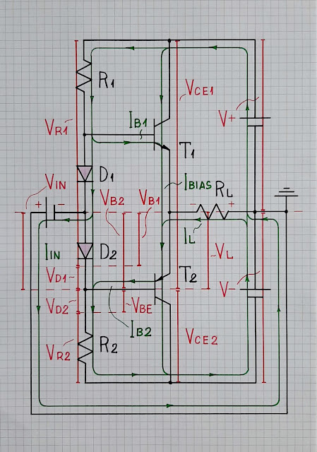
 This is  my answer  to SE EE question Class AB BJT biasing, diodes . My answer OP: "The voltage between the bases of transistors is highly dependent on the value of the resistors, even if both resistors are of the same value." This is actually the case when the input voltage applied to the midpoint between the diodes approaches the supply rails (large input signal). The problem of static quantities Static resistance. The problem can be that the resistors R1 and R2 have "static" (constant) resistance. And since the voltage applied across them varies considerably, the current through them varies and this causes the voltage across the diodes to vary as well. Static voltage. But the problem can be that the supply voltage Vcc is "static" (constant). And since the middle voltage Vmid considerably varies, the difference Vcc - Vmid = VR1 varies. This causes the current and eventually, the voltage across diodes to vary as well. The magic of dynamic quantities Dy...

Use Wheatstone bridge to measure unknown resistance

 This is  my answer  to SE EE question Use Wheatstone bridge to measure unknown resistance My answer A new look at the old bridge Can we now, in the 21st century, look at this famous 19th century device from a different perspective? Let's try... we won't lose anything from this... we will only gain… There were no precise sources then (neither voltage nor current)... nor precise voltmeters. So they had to find a way to compensate for the errors (mainly because of the varying supply voltage). For this purpose, they used the principle of negative feedback but implemented manually. So, the so-called "balanced bridge" and the man moving the rheostat's wiper or switching the resistors inside the box is a "negative feedback system". Its main purpose is to convert an unknown resistance Rx into another known (readable, measurable) resistance Rvar. It make it by keeping equal the ratios of two voltage dividers. From this point of view, the balanced bridge can be c...

Why does the TTL NAND gate use a 4 transistor design instead of 2?

Image
 This is  my answer  to SE EE question  Why does the TTL NAND gate use a 4 transistor design instead of 2 ? My answer Since the output part has been considered so far, I will make some assumptions about the input part that implements the logic function AND (NAND). Basic logic idea As a rule, basic logic functions OR and AND are implemented by connecting *electrically-controlled switches* in parallel and series. These techniques are widely used in MOS and CMOS logic gates... and also, in the second OP's circuit where transistors are used as switches. But how is this implemented in the first OP's circuit? Here, diode elements (T1's base-emitter junctions) are used as switches that, according to the rule, should be connected in series . But diode switches cannot be connected this way because they cannot be controlled. The problem of diodes is that they are 2-terminal (1-port) switches where the input and output occupy the same two terminals anode and cathode (base and e...

Why does this NPN transistor operate differently if it comes before the switched element?

 This is  my answer  to SE EE question  Why does this NPN transistor operate differently if it comes before the switched element ? My answer I want to further develop the philosophy inside some of the answers here making a few comparisons between the two circuits. In fact, both circuits are voltage followers but they follow different voltages - the first circuit "follows" the supply voltage V1 and the second circuit follows the input voltage V2. And because the supply voltage is higher than the input voltage, the current through the LED in the latter case is lower. If we continue with such simple comparisons, we can say that the transistor in the first circuit acts as a *closed switch* with zero resistance. No voltage is lost on it, so all the supply voltage is applied to the LED network. In the second circuit, the transistor acts as a *variable resistor* ("rheostat") on which, roughly speaking, the difference between the supply and input voltage is lost. Both circu...

What actually flows, current electricity or charge?

 This is  my answer  to SE EE question  What actually flows, current electricity or charge ? My answer To intuitively understand circuits, it is enough to realize that something like a pump (source) produces something like pressure (voltage) that causes something like fluid (electric current) to flow from where it is a lot (the positive source terminal) to where it is a little (the negative terminal) encountering obstacles (resistance) on its way. Then we need to realize what the connection between these pressure-like, flow-like and impediment-like quantities is (Ohm's law) and to see where currents flow (topology). Finally, it remains to be seen (in a most general way) what the basic circuit idea is.

LED wired to GPIO in an unconventional way

 This is  my answer  to SE EE question  LED wired to GPIO in an unconventional way ? My answer You can drive a LED (more precisely, a network of LED and resistor in series) in three possible ways: From the side of the anode (the cathode is grounded). Then high input voltage will light up the LED. The current will exit the upper transistor of the output and go through the LED to ground.  From the side of the cathode (the anode is connected to Vcc).  Then low input voltage will light up the LED. The current will exit Vcc, pass through the LED and enter the bottom transistor of the output. From both sides (both anode and cathode are connected to outputs like a bridge circuit).  Then only when there is high input voltage at the anode and low input voltage at the cathode, the LED will light up. The current will exit the upper transistor of the one output, go through the LED to and enter the bottom transistor of the other output. Simply speaking, the curren...

Where has this current gone in my current-voltage converter?

Image
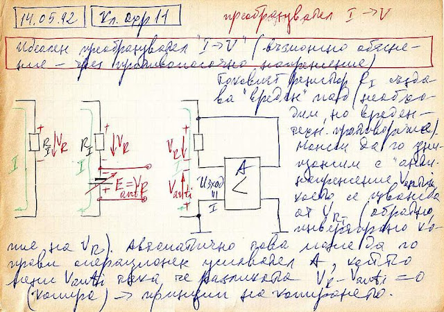
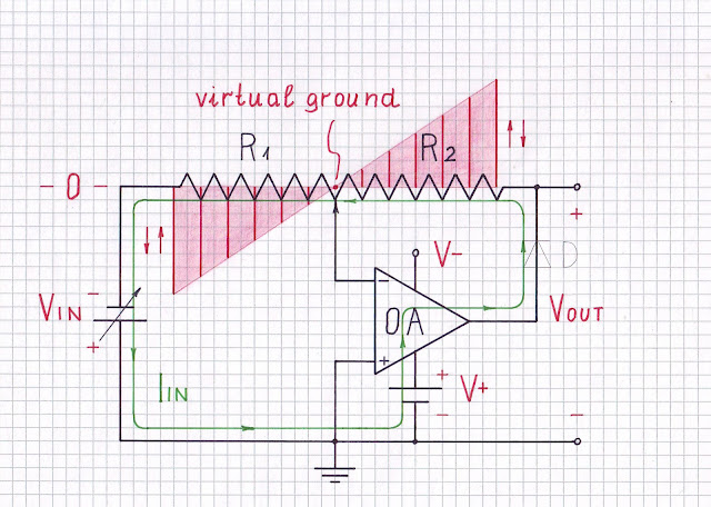
This is my answer to SE EE question Where has this current gone in my current-voltage converter ? My answer The necessary philosophy I read these answers full of technical details and wonder how it is possible not to reveal the simple but brilliant idea behind this op-amp circuit consisting only of a resistor and op-amp? I realized it 30 years ago (Fig. 1) and with its help I was able to understand and explain many other op-amp circuits. Fig. 1. A conceptual picture of an active current-to-voltage converter from my archive (1992). Here is the translated text: May 14, 1992. "Ideal" current-to-voltage converter (a possible explanation by an opposite voltage). The current-sensing resistor RI creates a "harmful" voltage drop VR (it is necessary but undesired; there is a contradiction). We can destroy it by an "anti voltage" V(E)anti that is subtracted from VR (it is an inverse copy of VR). It can be implemented by an op-amp A that adjusts Vanti so that VR - V...

Class AB power amplifier from "Electronic Devices" by Thomas L. Floyd

Image
This is  my answer  to SE EE question  Class AB power amplifier from "Electronic Devices" by Thomas L. Floyd . My answer Imagination is more important than knowledge. A. Einstein. How do we visualize the circuit operation? The notion of voltage as height is the most common idea of this electrical quantity (which is why we say "high" and "low" and not "big" and "small" voltage). It originates from the gravitational or "water tower" analogy where the height of a water column is proportional to the potential energy of the water. According to this approach, we can explain this circuit "geometrically" by imagining voltages as vertical segments ( voltage bars ) with a height proportional to the voltage value. It is well known that diodes maintain (approximately) constant voltage at their terminals (see this  intuitive explanation ). So, the voltage drops across them can be represented by segments of constant length (0.7 un...